
I recall a side comment by RAPT on a thread (that I haven't been able to find) regarding the appropriate use of compressive reinforcing for reducing long term creep and shrinkage deflections. As AS3600, CL 8.5.3.2 now clearly states that compression steel needs to be located in the compression zone (who would have thought! Amministrazione E Finanza Pdf Printer here. ) – I wanted to clarify the application of Asc in relation to slabs.
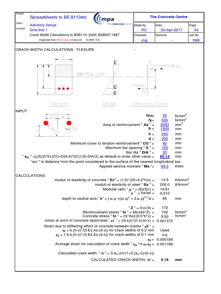
31, Max allowable design surface crack width (W) = 0.3, mm, (0.2 or 0.3 mm only), BS8007 specifies crack widths of 0.1 or 0.2 mm. Design by using Input Data Hw. When equilibrium water level is higher than the base level, buoyancy of the base due to displacement of water should be allowed in the stability calculation. Spur Gear Calculator (tooth profile design and strength) The gear calculator has been designed to help you optimise standard and non-standard spur gear configurations. May 11, 2017. Civil Engineering Spreadsheets. Abutment Column Design; ACI 318-08 Rec Sec. Mx -Q-Torsion Design; ACI 350 & ACI224R-01 Rectangular Section Flexural Crack Width Control; ACI 350.3-06 Seismic Loads for Liquid-Containing Rectangular RC Tank; AISC-ASD89 calculation for Beam-Column member. Sep 29, 2013. Helping us make and share calculations with MS Excel. XLC software to display MS Excel formulae in mathematical notation. Repository of solved problems covering many engineering topics. Site forum for software support and discussion of calculation. Engineering spreadsheets.
I had a quick look at Ku values for typical slabs that I have designed (deflection controlled) and Ku seems to generally be in the order of 0.1 (treating as singly reinforced). Adopting this value of Ku =0.1 and assuming 25mm cover and d = D – 25 – 10, the minimum slab thickness to just scrape any reinforcing into the compressive zone is D = 300mm (kud = 26.5mm). As this is based on a singly reinforced section – accounting for this 'compressive reinforcing' would actually lower Ku further (or does it – if it is not in compression?!). I have read that under sustained loading (ie appropriate to the consideration of long term deflections) the neutral axis lowers further as internal stresses are redistributed into the compression reinforcing – I have not found anything to quantify this however.
How do you determine the long term neutral axis depth and is this appropriate for the assessment of 'compressive reinforcing'. How far into the compression zone does reinforcing have to be to be effective - Should the reinforcing be located within the 'compressive stress block'? Is there a limit to how much compression reinforcing can be effective (right up to 100%)?
Should the Kcs reference be removed from the slab chapter (is it really on appropriate to beams)? What is industry practice?